I. Introduction
In domestic chemical, oil and gas, power station renovation projects, and foreign-related EPC projects implemented in China, a large number of original drawings for piping and fittings originate from foreign systems such as the American standard ASME, German standard DIN, and Japanese standard JIS, or are non-standard sketches formed from on-site surveying and mapping in earlier years.Such drawings generally have problems of inconsistency with the national standard system in nominal size marking rules, pressure rating logic, wall thickness series, flange bolt circle, material grades, groove forms, and inspection proportions.Many technical personnel adopt two extreme handling methods: one is to directly perform non-standard processing according to the original drawings, and later the special equipment supervision inspection and completion filing are rejected due to the lack of a national standard basis;the other is to forcibly replace them with similar specifications under the national standard, ignoring differences in strength, corrosion allowance, and opening reinforcement, leaving hidden dangers to pressure-bearing safety.
Converting non-standard drawings into national standards does not mean simply replacing dimensional numbers, but rather, under the premise of satisfying the boundary conditions of the original working conditions, aligning the structure, parameters, materials, and inspection rules to the national standard GB system, while distinguishing between equivalent standard conversion and retention of non-standard customization.TSG 31-2025 clearly states that pressure piping components shall preferentially use national standard standard parts;when standard parts cannot be selected, they shall be managed as compliant non-standard parts, with supporting drawings, strength calculation reports, and review documents.Mastering the complete set of skills for converting non-standard drawings to national standards is a key technical capability in drawing review, technical clarification, procurement material requisition, and manufacturing acceptance, and can effectively reduce the proportion of non-standard items, lower procurement costs, and shorten the supervision, inspection, and filing cycle.
II. Pre-judgment for non-standard drawing conversion: distinguishing scenarios that can be equivalently converted from those that cannot be converted
After receiving the drawings, the first step is not to directly change dimensions, but to carry out a feasibility judgment for conversion, which is the foundation of the entire conversion work.The input conditions for judgment include: design pressure, design temperature, medium, GC piping class, corrosion allowance, outer diameter of the connecting pipe, and connection boundary conditions.
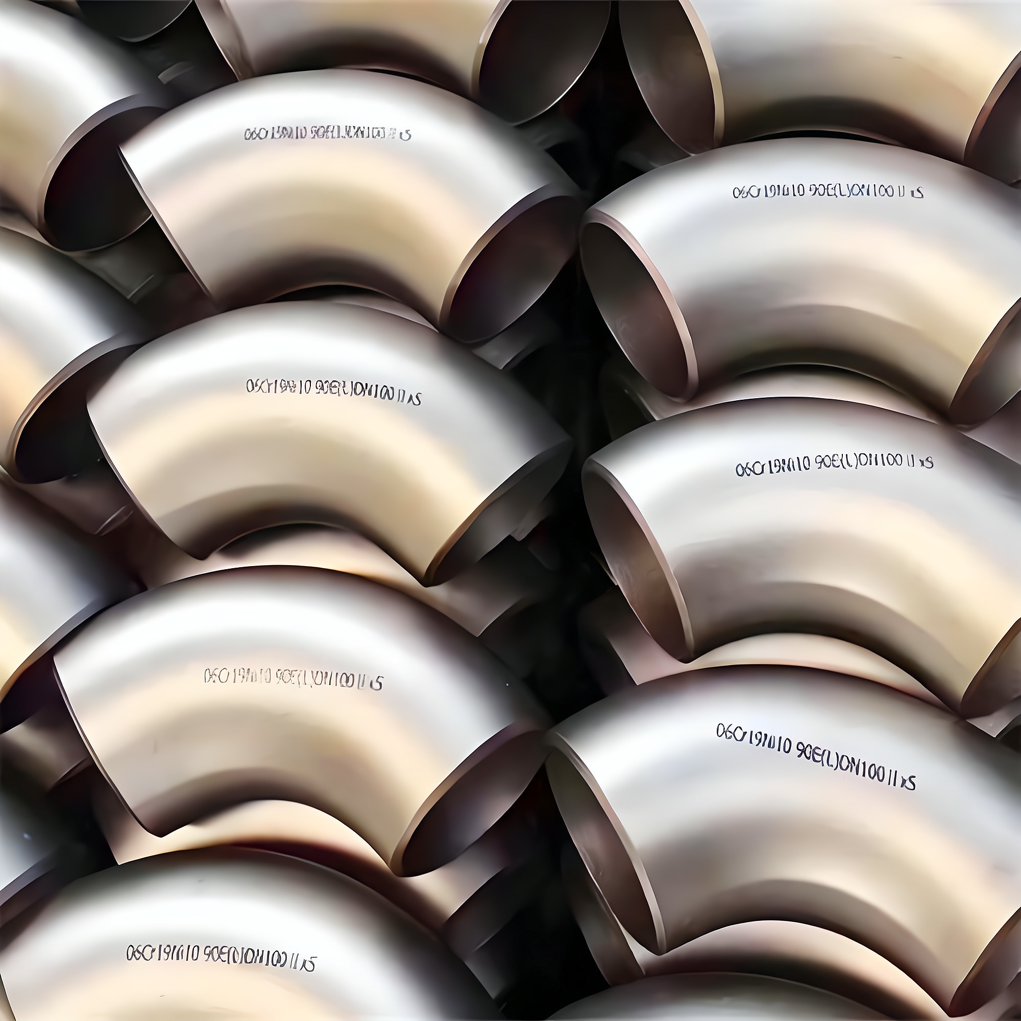
Category 1: Can be equivalently converted into national standard pipe fittings.The external structure of the pipe fitting belongs to the elbow, tee, reducer, cap, and flange structures covered by GB/T12459, GB/T13402, and HG/T20592. The non-standard nature of the original drawing comes only from differences in unit labeling, inch-to-metric conversion, approximate wall thickness, or old grade designation. The working load, opening reinforcement requirements, and the capability of national standard parts match, so through equivalent parameter conversion, it can be replaced with national standard specifications, and the drawing can be directly upgraded to a national standard part drawing and no longer controlled as non-standard.Typical scenario: For an ASME B16.9 elbow drawing, the NPS specification can correspond to the national standard DN. Under the premise that the temperature-pressure rating and corrosion allowance are consistent, select the same type of long-radius elbow under GB/T12459 as a replacement.
Category 2: The structure is special and cannot be converted into a national standard part; only the drawing is regularized according to national standards.The fitting structure itself is not included in the national standard finished fitting dimension tables, such as special-angle elbows, eccentric converging tees, non-standard bolt circle transition flanges, and large-opening reinforced branch outlets; there is no corresponding national standard finished product for these structural forms.At this point, national standard standard-part specifications cannot be forcibly applied. The goal of the conversion work is not to turn the item into a standard part, but to align drawing drafting specifications, calculation rules, material standards, and inspection clauses entirely with the national standard system, producing drawings as compliant custom non-standard parts under the national standard framework, accompanied by strength calculation reports.
Category 3: High-risk drawings prohibited from conversion.The original drawing's operating conditions involve GC1 highly toxic media, severe cyclic loading, and low-temperature fatigue conditions; the non-standard structural reinforcement form is special and has no national standard equivalent verification basis;or the original drawing is a simplified sketch lacking core inputs such as corrosion allowance, welded joint coefficient, and allowable stress, with missing data and no conditions for equivalent conversion; the non-standard review path should be maintained, and national standard standard parts must not be forcibly matched.
In the determination stage, a "Non-standard Drawing Conversion Review Form" must be produced, stating the original drawing source, original standard implemented, operating condition parameters, conversion conclusion, and equivalence basis, signed by the three parties of design, process, and quality control, to serve as the basis for subsequent drafting, procurement, and supervision, avoiding disputes caused by verbal conversion.
III. Practical Techniques for Item-by-Item National Standard Conversion of Core Parameters
(I) Conversion of Nominal Diameter, Outer Diameter, and Wall Thickness Series
Non-standard drawings commonly use inch NPS markings; for conversion to the national standard, the DN nominal diameter system should be adopted first.Key point to note: NPS and DN are not a one-to-one mathematical conversion but a matching of standard systems; you cannot simply multiply inches by 25.4 to obtain a value to use as the outer diameter.For example, NPS2 cannot be simply converted to 50.8 mm; it should be matched to the steel pipe outer diameter series corresponding to national standard DN50.During conversion, priority should be given to ensuring that the outer diameters of the butt-jointed straight pipes are consistent to guarantee matching at the joint; the outer diameter priority principle takes precedence over nominal designation matching.
Wall thickness conversion is a high-frequency error point.The overseas SCH wall thickness series and the national standard GB/T20801 wall thickness value logic are different; SCH is a US standard system series based on pressure and temperature, while national standard wall thickness requires recalculation of corrosion allowance, steel plate negative deviation, and forming thinning allowance.The SCH wall thickness values cannot be directly transferred onto national standard drawings.Correct technique: extract the design pressure, temperature, and corrosion allowance from the original drawing, recalculate according to the GB/T20801 wall thickness calculation formula, ensure the recalculated minimum wall thickness is not lower than the pressure-bearing capacity of the original drawing, and then select the national standard wall thickness;If the standard wall thickness specified in the national standard cannot be met, retain the non-standard wall thickness, and classify the drawing as a non-standard part under the national standard system.
(II) Conversion of pressure ratings and flange systems
There is no fixed conversion formula between Class pound ratings and PN kilogram ratings; many drawings directly state Class150=PN20, which is a typical error.Conversion technique: do not perform simple numerical equivalence; instead, use temperature-pressure tables for comparison, and at the project design temperature, perform an equivalent comparison between the maximum allowable pressure corresponding to the Class rating and the rated pressure of the national standard PN flange at the same temperature.For flanges, give priority to aligning with the HG/T20592 national standard European standard flange system or the HG/T20615 American standard flange system; the system must be unified, and flanges from different systems must not be mixed within one drawing.
Conversion of non-standard flange drawings: if only the bolt hole circle diameter and the number of bolts are non-standard, but the material and sealing face type conform to the basic national standard specifications, priority should be given to evaluating modification of the bolt circle to match national standard flanges;if the equipment interface imposes hard constraints and the bolt circle cannot be modified, then the flange structure remains non-standard, but the flange material, sealing face dimensions, thickness calculation, and test requirements on the drawing shall all be prepared in accordance with the national standard GB and HG specifications.
(III) Equivalent conversion of material grades to national standards
Foreign material grades such as A105, 304, 15Mo3, St37, etc., cannot be directly replaced with approximate national standard grades during conversion; the chemical composition, mechanical properties, high-temperature allowable stress, and impact test requirements must be verified.Equivalent substitution must satisfy the following: the allowable stress within the same temperature range is not lower than that of the original grade, the corrosion resistance under corrosive environments is comparable, and the heat treatment requirements match.For example, A105 is equivalent to Q355NB, and 16Mo3 corresponds to 15CrMo; a grade equivalence comparison table must be attached in the technical documents, and according to the requirements of TSG31, the material substitution equivalence scheme must be approved by the design unit.It is strictly prohibited for procurement to make verbal equivalent material substitutions on their own.
(IV) National standardization of groove, tolerance, and dimensioning systems in drawings
The groove, dimensioning, and tolerance marking conventions in many foreign non-standard drawings are inconsistent with the domestic drafting standard GB/T4458.4.Conversion techniques: end-face grooves shall be dimensioned according to the welding groove types and angles specified in GB/T20801 and GB/T12459;Dimensional tolerances shall no longer follow the ASME tolerance tables and shall be replaced with national standard tolerances for pressure pipe fittings;The drawing title block, technical requirements, marking method, stamp content, and non-destructive testing symbols shall all be rewritten in accordance with domestic pressure piping drafting specifications.Drawing annotations must clearly specify: design pressure, design temperature, medium, corrosion allowance, welded joint coefficient, and the applicable national standard number, eliminating vague descriptions in the original drawings.
IV. Strength verification, inspection clauses, and document package conversion techniques
Completing parameter replacement does not mean the conversion is complete; pressure-bearing safety verification is a mandatory step in the conversion.For items converted to national standard parts, the type verification basis of the national standard can be directly cited, and separate strength calculations are not required;If the converted item still remains a non-standard part, a new strength calculation report must be issued in accordance with the stress calculation method of GB/T20801, including wall thickness verification, branch opening reinforcement verification, flange sealing verification, and reducer cone angle verification; GC1 piping also requires stress analysis review.
Inspection and test clauses shall be converted accordingly: the NDT inspection ratio, acceptance level, and hydrostatic test pressure in the original drawings must not be directly copied from foreign standards; they shall be converted to the requirements of JB/T4730 non-destructive testing and GB/T20801 pressure testing.For example, if the original drawings use the inspection ratio of ASME Section VIII, after conversion they must match domestic pressure piping supervision and inspection requirements, and the technical requirements column shall state the applicable national standard testing standard, acceptance level, test medium, and pressure holding time.
Documentation system conversion techniques: the original drawing certificate templates, the language of quality certification documents, and all inspection items must be adjusted to the format recognized by domestic special equipment supervision and inspection.For those converted to standard parts, the quality certificate shall reference finished pipe fitting standards such as GB/T12459;For those retaining non-standard structures, the documentation shall state "designed and manufactured in accordance with this drawing and GB/T20801," and shall not simultaneously mark overseas finished pipe fitting standards, so as to avoid contradictions in supervision and inspection documentation.
V. High-frequency pitfalls and risk prevention in drawing conversion
Pitfall 1: Directly converting NPS to millimeters and Class to PN, looking only at numerical equivalence while ignoring temperature-pressure derating characteristics.Prevention: Establish a project-specific temperature-pressure equivalent comparison table, using the allowable pressure-bearing capacity at the same temperature as the basis for equivalence determination, rather than static numerical conversion.
Pitfall 2: Assuming equivalence based on approximate material grades without verifying high-temperature allowable stress and impact requirements, creating failure risks under high-temperature, hydrogen-service, and low-temperature conditions.Prevention: Grade equivalence must be accompanied by a material performance comparison table and reviewed by a materials engineer; the material equivalence plan for GC1 piping must be design-approved.
Misconception 3: For non-standard tees and branch outlets with complex structures, forcibly simplify and modify the structure, and apply national standard tee standard parts.Prevention and control: As long as the opening reinforcement structure and branch proportion exceed the scope of the national standard table, they must not be forcibly converted into standard parts; instead, follow the non-standard review process under the national standard framework.
Misconception 4: Conversion only changes drawing dimensions, while inspection, pressure testing, and documentation clauses remain unchanged from overseas standards, causing supervisory inspection agencies to reject them.Prevention and control: Drawing conversion is the conversion of the entire technical system; drawings, technical requirements, inspection plans, and quality documents must be aligned with national standards simultaneously.
Misconception 5: For non-standard drawings surveyed and mapped for modification projects, only external dimensions are matched, current operating parameters are not rechecked, and national standard specifications are directly applied.Prevention and control: Before converting surveyed and mapped drawings, recheck the current design parameters, update the corrosion allowance according to the current medium, and do not carry over old operating conditions.
VI. Review, sample sealing, and procurement implementation control of converted drawings
After drawing conversion is completed, implement a three-level review process: draftsman self-check, process verification, and review by the technical responsible person; for high-risk pipelines such as GC1, add an approval step.Key review points: working condition matching, equivalence basis, strength calculation, material equivalence, inspection clauses, and marking specifications.After the review is passed, the drawing version shall be frozen, and the conversion version number shall be marked as the basis for procurement and manufacturing. Any parameter change must be re-reviewed.
The procurement side shall implement synchronized supporting control: for items determined after conversion to be national standard standard parts, inquiries shall be made directly according to national standard specifications, enjoying the advantages of batch stock availability and low prices;for items determined to be non-standard parts under the national standard system, the technical agreement shall clearly specify the drawing version, calculation book delivery, supervision during manufacturing, and NDT requirements, and the supplier must hold a pressure piping component manufacturing license.After the first article is manufactured, a sealed sample shall be retained to check dimensions, groove, and markings, verify the conversion effect, and avoid batch deviations.
VII. Conclusion
The core skill in converting non-standard drawings of pipes and fittings to national standards is not simply modifying dimension markings, but rather prioritizing working conditions, equivalent pressure-bearing capacity, and classified handling: those with matching structures and satisfied loads shall be preferentially converted into national standard standard parts to simplify control and reduce procurement costs;for those with special structures that cannot be classified into finished product standard tables, the drawing standardization transformation shall be completed under the safety framework of national standards GB/T20801 and TSG31, and they shall be managed as compliant customized non-standard parts, supported by strength calculations and technical review.
The complete conversion process consists of eight major steps: feasibility determination, nominal size and wall thickness conversion, pressure flange equivalence, material grade cross-referencing, drawing annotation standardization, strength verification, inspection clause conversion, and drawing review.Proficient use of this conversion method can effectively solve the compliance challenges of implementing overseas drawings and old non-standard surveyed and mapped drawings in domestic projects, reducing issues such as supervisory inspection rejection, filing obstruction, assembly misalignment, and material mismatch, while balancing procurement economy with the safety bottom line of pressure piping special equipment, and adapting to various pipeline renovation and foreign-related implementation projects in chemical, oil and gas, power station, and new energy sectors.
References
[1] TSG 31-2025, Safety Technical Regulation for Industrial Piping [S]. State Administration for Market Regulation, 2025.
[2] GB/T 20801-2020, Pressure Piping Code — Industrial Piping [S]. Beijing: Standards Press of China, 2020.
[3] GB/T 12459-2017, Steel Butt-Welding Seamless Pipe Fittings [S]. Beijing: Standards Press of China, 2017.
[4] HG/T 20592-2009, Steel Pipe Flanges, Gaskets and Fasteners [S]. Beijing: Chemical Industry Press, 2009.
[5] GB/T 4458.4-2003, Mechanical Drawings — Dimensioning [S]. Beijing: Standards Press of China, 2003.
[6] ASME B16.9-2021, Factory-Made Wrought Butt-Welding Fittings [S]. New York: ASME Press, 2021.
[7] Li Gang. Practical Guide to Pressure Piping Component Design and Non-Standard Component Review [M]. Beijing: Atomic Energy Press, 2021.