Introduction
In engineering fields such as pulverized coal conveying in thermal power generation, mine tailings backfill, metallurgical slurry conveying, dredging and sand pumping, and ash and slag conveying in coal chemical industry, the medium inside the pipeline is mostly solid-liquid or gas-solid two-phase fluid, and solid particles continuously scour the pipe wall, causing the pipe wall to gradually thin; the wear rate at elbows, tees, and branch pipe locations is much higher than that of straight pipe sections.Under high-wear conditions, ordinary carbon steel pipelines have a short service life and frequently suffer pipe bursts and leaks, causing production shutdowns for maintenance, material loss, and safety and environmental accidents.Long-term engineering practice shows that the failure of wear-resistant pipelines is often not simply due to insufficient material hardness, but rather because the wear mechanism, material characteristics, and operating condition boundaries were not distinguished during the selection stage; simply relying on hardness indicators for selection and ignoring coupling factors such as impact toughness, temperature, medium corrosion, flow velocity, and particle size leads to premature spalling, fracturing, and cracking of wear-resistant parts.
A wear-resistant pipeline system includes a complete set of pipe fittings such as straight pipes, elbows, tees, reducers, pipe caps, and flanges; the selection for the entire pipeline must maintain consistency in the material system, wear-resistant structure, and connection method, and straight pipes and pipe fittings must not use different wear-resistant types.There are several prominent problems commonly found in industry procurement: using hardness as the sole selection indicator and ignoring the risk of brittle spalling of ceramic linings under large-particle impact conditions;failing to distinguish among abrasive wear, impact wear, and corrosive wear mechanisms, and mixing rubber lining, ceramics, bimetals, and polymer wear-resistant materials;technical agreements lack key indicators such as wear testing, interfacial bond strength, and wall thickness reduction limits;Procurement only focuses on the initial purchase unit price and has not carried out a full life cycle cost assessment;There is a lack of dedicated inspection for interface defects, lining layer cracks, and delamination peeling of wear-resistant composite pipe fittings.
The selection of wear-resistant pipe fittings is a systematic engineering process, covering the entire chain of operating condition parameter collection, wear mechanism determination, material matching, structural optimization, wall thickness verification, connection design, factory inspection, incoming acceptance, and operation monitoring.This article systematically elaborates on the basic standards for the selection of wear-resistant pipeline fittings from the aspects of wear mechanisms, operating condition classification, wear-resistant material systems, pipe fitting structure selection, wall thickness and flow channel design, connection and sealing schemes, inspection and test requirements, procurement technical agreements, selection misconceptions, and full life cycle evaluation, providing a standardized technical basis for the procurement of wear-resistant pipe fittings in EPC projects, mines, power plants, and chemical projects.
I. Wear Mechanisms of Wear-Resistant Pipelines and Standards for Operating Condition Classification
1.1 Basic Wear Mechanisms
The wear of industrial wear-resistant pipelines is mainly divided into four categories, and most operating conditions in engineering involve the superposition and coupling of multiple types of wear.
The first category is abrasive wear.Fine solid particles slide and scrape along the pipe wall under fluid drag, forming groove-like wear at the bottom of the pipeline.This is mostly seen in low-velocity slurry transport and tailings backfill pipelines; the wear rate is directly related to particle hardness and particle concentration.
The second type is erosive wear.Fluid carrying particles impacts the pipe wall at high speed, causing cutting-type material removal at the outer side of elbows and at tee branch points.Flow velocity has an exponential effect on erosive wear; when flow velocity doubles, the wear rate usually increases several times, making it the most common failure mode in gas-solid pneumatic conveying and high-pressure slurry pipelines.
The third type is impact wear.Large-diameter, high-density particles impact the pipe wall at a large angle, and the impact load causes plastic deformation of the material and initiation of microcracks.Ceramic-lined pipe fittings are highly prone to liner cracking and detachment under severe impact conditions.For impact conditions, material selection must not only pursue high hardness but must also take fracture toughness into account.
The fourth category is corrosion-wear coupled wear.The medium contains both solid particles and acid-base corrosive components; corrosion damages the passivation film on the pipe wall surface, and particle erosion continuously strips away the corrosion layer. Through their synergistic effect, the wear rate is far higher than that of single wear or single corrosion.This type of condition is commonly found in wet desulfurization slurry and acidic ore slurry pipelines.
1.2 Condition Classification and Pre-selection Parameters
Before selection, the basic parameters of the working condition must be fully collected as inputs for the selection decision. Without sufficient parameters, the type of wear-resistant pipe fitting cannot be directly determined.The parameters to be collected include: medium type; solid-phase particle material, hardness, particle size distribution, particle shape, and solid mass concentration;medium temperature, pH value, and corrosive components;Medium flow rate, pressure;Pipeline layout forms (horizontal straight pipe, vertical riser, elbow, tee); particle impact angle; design service life; Installation space, maintenance conditions.
Based on the severity of wear, it can be divided into four levels: mild wear, moderate wear, severe wear, and strong impact wear.Mild wear: fine particles, low flow rate, no strong impact, low wear rate;Moderate wear: conventional tailings, fly ash slurry, small particle size, weak impact;Severe wear: high-concentration slurry, pneumatic conveying of pulverized coal, high particle hardness, high flow velocity;Strong impact conditions: coarse aggregate backfilling, chute discharge outlets, large particles impacting the inner wall of pipe fittings at high speed; pure ceramic-lined pipe fittings are not recommended for such conditions.
During the condition assessment stage, CFD fluid erosion simulation shall be carried out when necessary to predict the maximum wear rate at elbows, tees and other locations, determine local thickening areas, and provide a basis for the structure and wall thickness design of pipe fittings.Elbows are the most severely worn parts. Under erosion conditions, the outer arc surface of the elbow is the core wear area, and local thickening or the use of special wear-resistant elbows is usually required.
II. Mainstream material systems for wear-resistant pipeline fittings and applicable condition standards
Currently, engineering wear-resistant pipe fittings are mainly divided into four categories: wear-resistant cast steel/surfacing-welded metal wear-resistant pipe fittings, ceramic-lined composite pipe fittings, polymer wear-resistant composite pipe fittings, and rubber-lined wear-resistant pipe fittings. Different materials have clear applicable boundaries, and selection must strictly match the working conditions.
2.1 Metal wear-resistant pipe fittings
1. Wear-resistant cast steel pipe fittings: high-chromium cast iron KmTBCr26, wear-resistant alloy steel, high-manganese steel, etc.High-chromium cast iron has high hardness and excellent wear resistance, but it is brittle and has poor weldability, making it suitable for pulverized coal and ash/slag conveying at medium temperatures and moderate impact;High-manganese steel undergoes work hardening under strong impact, making it suitable for working conditions with large particles and strong impact, but its wear resistance advantage is not obvious under low-impact conditions.
2. Bimetallic composite wear-resistant pipe fittings: the outer layer is a pressure-bearing carbon steel base, and the inner wall uses a high-chromium alloy centrifugal casting composite layer; the base bears the pressure, and the inner layer provides wear resistance.The interface is metallurgically bonded, not prone to delamination or peeling, and can be welded. It is suitable for high-temperature, high-pressure, high-wear, medium-impact slurry and ash/slag pipelines, and is a commonly used solution for high-pressure wear-resistant pipelines in thermal power and mining.
3. Surfacing-welded wear-resistant pipe fittings: a chromium carbide wear-resistant layer is surfacing-welded onto the inner wall of a carbon steel base; the thickness of the wear-resistant layer is controllable, and on-site repair welding is possible.The advantage is that local repair is possible, making it suitable for pipelines with uneven wear that require on-site repair;The disadvantage is that residual stress exists in the surfacing-welded layer, and excessive impact can easily cause cracks in the surfacing-welded layer.
4. Pipe fittings rolled from ordinary wear-resistant steel plates, such as NM400, NM450, and NM500 wear-resistant steels, are suitable for large-diameter pipelines with moderate wear and low pressure that are convenient for on-site processing.
Common advantages of metal wear-resistant pipe fittings: high temperature resistance, strong pressure-bearing capacity, and weldability;The disadvantages are relatively high dead weight, and service life under high-wear conditions is lower than that of ceramic composite pipe fittings.
2.2 Ceramic-lined composite pipe fittings
Ceramic composite pipe fittings use ordinary steel pipes as the pressure-bearing substrate, and the inner wall relies on an aluminothermic self-propagating reaction to generate an Al₂O₃ ceramic wear-resistant layer. The ceramic layer has extremely high hardness, and its wear resistance far exceeds that of ordinary steel. It is suitable for working conditions with fine particles, high flow velocity, and low impact, and is widely used for the transportation of pulverized coal, fly ash, and fine tailings slurry.
The selection constraint is impact resistance.When the medium contains large-particle coarse aggregate and the impact energy is relatively high, the ceramic layer is prone to cracking and spalling. Once the ceramic layer partially detaches, the substrate steel pipe will quickly be eroded and perforated.During procurement, the interfacial shear strength between the ceramic layer and the steel substrate must be verified; insufficient interfacial bonding strength will cause overall peeling of the ceramic layer.ZTA zirconia-toughened alumina ceramic lining has better toughness than ordinary alumina ceramics and is suitable for working conditions with a certain degree of impact.The applicable temperature of ceramic pipe fittings is generally not higher than 400°C, and severe temperature fluctuations can also cause cracking of the ceramic layer.
2.3 Polymer wear-resistant pipe fittings (ultra-high molecular weight polyethylene UHMW-PE)
Ultra-high molecular weight polyethylene pipe fittings have a low friction coefficient, excellent wear resistance, impact resistance, corrosion resistance, light weight, and convenient installation.Suitable for room-temperature ore slurry, tailings, dredging mud, and fine-particle slurry transportation.The limitation lies in the low upper temperature limit, generally not exceeding 80°C, and limited pressure-bearing capacity; they cannot be used in high-temperature working conditions or in high-temperature gas-solid conveying pipelines.At the same time, they must not come into contact with strong organic solvents.
2.4 Rubber-lined wear-resistant pipe fittings
Lined with natural rubber or butyl rubber, they are wear-resistant while also having excellent corrosion resistance, suitable for room-temperature acidic and alkaline slurries and fine-particle ore slurry transportation.Rubber lining has limited resistance to particle cutting and is not suitable for media with sharp, angular, large particles;The service temperature must not be too high, as high temperatures accelerate rubber aging, bulging, and delamination.
Basic criteria for material selection: for strong impact, high-manganese steel and bimetallic materials are preferred;for high temperature and high pressure, bimetallic and wear-resistant alloy steel are preferred;for fine particles and low impact, ceramic composites are preferred;for room-temperature corrosive slurries, rubber lining or UHMWPE is preferred.Material wear resistance and hardness alone cannot be used as the sole basis for selection; materials with high hardness often have poor toughness and are actually more prone to failure under impact conditions.
III. Structural Selection Standards for Wear-Resistant Pipe Fittings
Wear-resistant pipe fittings include elbows, tees, reducers, branch outlets, pipe caps, etc. The structural design directly affects wear distribution and service life. Structural selection must follow the principles of fluid mechanics to reduce local turbulence and particle impact.
3.1 Elbow Selection Standards
Elbows are the pipe fittings subject to the most severe wear. For selection, long-radius elbows with large curvature should be preferred, R≥1.5D;For high-wear slurry and pneumatic conveying conditions, extended long-radius elbows with R=2D and R=3D are recommended to reduce the particle impact angle and decrease erosive wear.Short-radius elbows are strictly prohibited for severe erosion conditions.The worn area on the outer side of the elbow needs local thickening, and the thickening amount is determined based on erosion calculation results.For ceramic composite elbows and bimetallic elbows, the wear-resistant layer thickness should be uniform, and thinning of the lining and cracks are not allowed at the curved section.For pipelines conveying coarse particles with strong impact, arc-shaped flow-guiding wear-resistant elbows and elbows with wear-resistant guard plates can be used to change the particle flow trajectory and reduce direct impact on the pipe wall.The end face beveling of elbows must ensure smooth butt welding; weld beads and misalignment on the inner wall will cause local eddy currents and greatly aggravate wear. The inner walls of butt-jointed wear-resistant pipes must be flush to reduce internal convex weld seams.
3.2 Tee selection standards
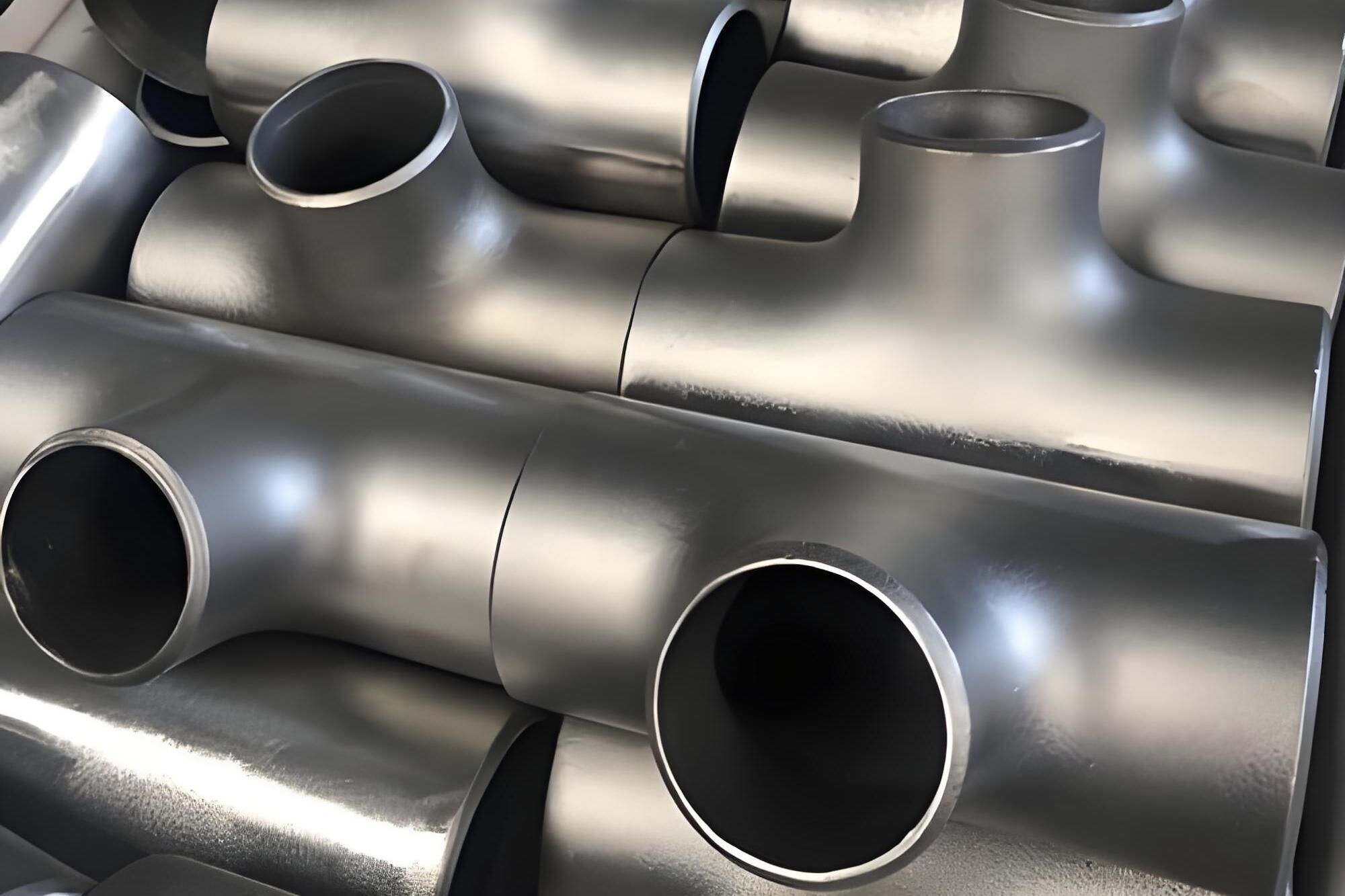
Conventional equal-diameter tees have internal fluid impact and eddy currents, and the wear at the branch junction is severe.For high-wear conditions, priority should be given to mitered flow-guide tees and Y-type tees to reduce the medium's perpendicular impact on the pipe wall;avoid T-type right-angle tees.In T-type tees, the medium impacts the side wall perpendicularly, causing severe impact wear, so they are only suitable for light-wear conditions.The wear-resistant layer on the inner wall of the tee must be continuous and complete, and the wear-resistant layer at the junction corners must not be interrupted. The corners of composite pipe fittings are the parts where the lining layer is most prone to cracking, so they should be key inspection points during procurement acceptance.
3.3 Reducers, branch outlets, and pipe caps
Reducers shall use concentric or eccentric tapered types, with a gentle transition in the conical section to avoid abrupt cross-section changes that form vortices; abrupt steps will cause localized high-speed erosion.For branch connections, avoid vertical drilled branches as much as possible; the intersection area of vertical branches suffers severe wear. When necessary, use integrally forged wear-resistant branch outlets with smoothly rounded inner wall transitions.Pipe caps shall preferably use an elliptical integrally formed wear-resistant structure, and flat plate welded heads shall not be used, as the bottom of a flat plate head directly bears particle impact.
3.4 Flow passage consistency of the complete set of pipe fittings
For the complete wear-resistant pipeline, the inner diameters of straight pipes, elbows, tees, and reducers must remain consistent. Abrupt changes in inner diameter will cause localized flow velocity changes and vortices, aggravating localized wear.Inner diameters from different manufacturers are prone to mismatch, so wear-resistant pipe fittings are recommended to be purchased as a complete packaged set to ensure continuous and smooth flow passages.
IV. Wall thickness design and wear allowance verification standards
The wall thickness of wear-resistant pipe fittings consists of two parts: the pressure-bearing base wall thickness + the wear-resistant layer thickness, while also reserving a wear allowance. The wall thickness calculation formulas for ordinary pressure piping must not be used.The base steel pipe shall be subject to pressure strength calculation in accordance with GB/T20801 and ASME B31.3 to meet the pressure-bearing strength requirements;The thickness of the wear-resistant layer is determined based on the wear rate and the design service life;The wear allowance is the core of selection, used to compensate for material wear thinning during service.
Calculation of wear allowance: multiply the medium wear rate by the design life, then add a safety factor.For severe wear conditions, the wear allowance value shall be increased.In the procurement technical agreement, the minimum allowable remaining wall thickness must be clearly specified, online wall thickness monitoring points shall be set up, thickness measurement monitoring points shall be set at the outer side of elbows and at tee intersections, regular inspections shall be conducted, and timely replacement shall be carried out when the remaining wall thickness falls below the limit.
Composite pipe fittings require distinguishing between the base wall thickness and the wear-resistant layer thickness; the wear-resistant layer must not be counted as pressure-bearing wall thickness, as the pressure-bearing strength is borne by the outer metal base.Ceramic lining, rubber lining, and polymer lining serve only as wear-resistant and anti-corrosion layers and do not bear internal pressure loads. This is a very common misconception in procurement, and many projects incorrectly count the lining thickness as pressure-bearing wall thickness, creating safety hazards.
V. Standards for Pipe Fitting Connections, Flanges, and Sealing Selection
The connection forms of wear-resistant pipe fittings are divided into butt-welded connections, flanged connections, and clamp-type quick-install connections; the selection depends on pressure, temperature, medium, and maintenance frequency.For high-pressure and high-temperature working conditions, butt-welded connections are preferred; the inner wall of the weld seam should be ground smooth to eliminate weld beads, as weld beads will create turbulence and accelerate wear;For low-pressure pipelines that require frequent disassembly and maintenance, flanged connections are selected.
Flange selection: for severely worn pipelines, neck butt-welded flanges are recommended to reduce stress concentration at the root.The lining layer at the flange face of composite wear-resistant pipe fittings must extend completely to the sealing surface, and there must be no discontinuity in the lining.Gasket selection should take into account wear-resistant media, temperature, and corrosion;Gaskets for slurry media need to have resistance to solid particle erosion to prevent particles from intruding into the gasket and causing sealing failure.For polymer and rubber-lined wear-resistant pipe fittings, the flange flanging process is critical; the lining at the flanged position is prone to tearing and delamination, so factory inspection focuses on verifying the flanging quality.
Clamp connections are mostly used for UHMWPE and rubber-lined low-pressure wear-resistant pipelines; installation is quick, but the pressure rating is limited, making them unsuitable for high-pressure conditions.Regardless of the connection type, the core principle is: the inner wall at the joint must be smooth with no steps, eliminating local eddy-current wear sources.
VI. Requirements for Inspection, Testing, and Factory Documentation of Wear-Resistant Pipe Fittings
The inspection system for wear-resistant pipe fittings is divided into base material inspection, wear-resistant layer inspection, interface performance inspection, dimensional inspection, hydrostatic test, non-destructive testing, and wear resistance testing. The interface performance testing of composite wear-resistant pipe fittings is the core item that distinguishes them from ordinary pipe fittings.
Inspection of metal wear-resistant pipe fittings: chemical composition of base material, mechanical properties, impact test, hardness testing;RT/UT non-destructive testing of welds; Hydrostatic strength test; Dimension and wall thickness inspection;MT surface inspection of the surfacing layer to check for cracks in the surfacing layer.
Special inspection of ceramic composite pipe fittings: appearance of the ceramic layer, cracks and holes are not allowed;Ceramic layer thickness inspection;Interfacial shear strength test; Hydrostatic pressure test; Tap inspection to determine whether there is lining debonding or delamination.Cracks in the ceramic layer and interfacial debonding are fatal defects, and rapid failure will occur after being put into operation.
Rubber-lined and polymer pipe fittings: visual inspection of the lining, spark testing (pinhole detection) to detect tiny pinhole defects in the lining;dimensions, wall thickness, tensile and wear resistance tests; hydrostatic burst test.
List of factory delivery documents: base material quality certificate, heat number, mechanical properties and hardness report;wear-resistant layer inspection report;interfacial bond strength test report;spark test report; non-destructive testing report; Dimensional and wall thickness records; Hydrostatic pressure test report; Wear resistance performance test report; Product drawings; Installation and operation technical manual.For the supervision project of wear-resistant pipe fittings, the purchaser shall arrange factory supervision, focusing on verifying the forming process of the wear-resistant layer, interface inspection, and lining integrity.During the incoming acceptance stage, visual inspection, wall thickness sampling inspection, and electric spark pinhole sampling inspection shall be carried out; acceptance shall not be granted if the documents are incomplete or the sampling inspection fails.
VII. Core Clauses of the Technical Agreement for Procurement of Wear-Resistant Pipe Fittings
Wear-resistant pipe fittings procurement contract and technical agreement, requiring complete inclusion of operating condition description, wear mechanism, material grade, wear-resistant layer indicators, structural form, radius of curvature, wear allowance, inspection items and acceptance criteria, factory document list, supervision requirements, material substitution approval, and warranty responsibilities.
The technical agreement must clearly specify: it is prohibited to count the wear-resistant layer into the pressure-bearing wall thickness;local thickening requirements for elbows and tees;control limits for internal wall misalignment and weld bead;interface strength and spark leak detection requirements for composite pipe fittings;setting of wear monitoring points;wear life guarantee clauses.It is agreed in the contract that if the wear-resistant pipe fittings suffer early liner detachment or abnormal wear perforation due to selection or manufacturing defects, the supplier shall bear replacement and shutdown losses.Procurement bidding evaluation cannot rely solely on price comparison; it must assess the supplier's track record in similar wear-resistant pipeline projects, wear-resistant material manufacturing processes, and inspection capabilities.Wear-resistant pipe fittings are special pipe fittings; low-priced products often reduce the thickness of the wear-resistant layer and simplify interface inspection, causing premature project failure and a substantial increase in full life-cycle costs.
VIII. Common Misconceptions in Selection and Procurement of Wear-Resistant Pipe Fittings
Misconception 1: The higher the hardness, the better; only looking at hardness indicators while ignoring toughness.High-hardness ceramics and high-chromium cast iron have low toughness and shatter rapidly under strong impact conditions, resulting in very short service life instead.The core of wear selection is matching the wear mechanism, not simply pursuing high hardness.
Misconception 2: Including the inner wear-resistant lining layer in the pressure-bearing wall thickness.Ceramic, rubber, and polymer linings do not bear pressure; pressure bearing relies on the external metal base body. This error will cause insufficient pressure resistance and the risk of pipe bursting.
Misconception 3: Straight pipes and pipe fittings are purchased separately from different manufacturers, resulting in inconsistent inner diameters, steps at the interfaces that generate eddies, and rapid localized wear.
Misconception 4: No wear allowance is reserved, and procurement is based on the nominal wall thickness from static drawings; after operation, the pipe wall gradually thins and reaches the scrapping thickness in a short time.
Misconception 5: The coupled effect of corrosion and wear is ignored, with only wear resistance considered and no consideration of acid-base corrosion by the medium; corrosion accelerates material spalling, and the wear rate increases several times over.
Misconception 6: Internal weld beads and misalignment at welds are neglected, and welding is regarded as merely a construction issue; in fact, protrusions on the inner wall are an important cause of erosive wear, and wear-resistant pipes must require flush grinding of the inner wall.
Misconception 7: No interface inspection is performed; ceramic and rubber-lined composite pipe fittings are only visually inspected, and voids and interface debonding cannot be identified by the naked eye, leading to large-area spalling of the lining after commissioning.
Prevention and control measures: Carry out an operating condition assessment in the early stage of the project to determine the wear mechanism;purchase the complete set of wear-resistant pipes and fittings uniformly to ensure flow passage matching;and specify the wear allowance and special interface inspection in the technical agreement;Factory supervision during manufacturing, incoming electrical discharge and wall thickness spot checks;Establish a regular thickness measurement monitoring plan during operation to predict remaining service life in advance.
IX. Full Life Cycle Economic Evaluation of Wear-Resistant Pipe Fittings
The selection of wear-resistant pipe fittings cannot rely solely on comparing initial purchase prices; a full life cycle cost calculation is required, including procurement cost, transportation and installation, downtime maintenance, spare parts replacement, and leakage losses.Ceramic composite pipe fittings have a high purchase unit price, but their wear-resistant life is long, and the replacement frequency during long-term operation is low;Ordinary wear-resistant carbon steel is low in price, but requires frequent replacement, resulting in large downtime losses.For severe-wear long-distance conveying pipelines, the comprehensive economics of ceramic and bimetallic composite pipe fittings are often superior to ordinary wear-resistant steel.
At the selection stage, establish a life comparison model that integrates procurement, maintenance, and production shutdown losses to determine the optimal solution.For short-term temporary projects with low wear levels, economical wear-resistant steel can be selected;For long-term continuous production and main conveying pipelines in mines and power plants where downtime losses are huge, high-lifespan composite wear-resistant pipe fittings should be prioritized.
X. Conclusion
The failure of wear-resistant pipe fittings is the result of coupled multi-factor effects including solid particle erosion, abrasion, impact, and corrosion. The core of selection is to identify the wear mechanism and match material toughness, hardness, temperature resistance, and corrosion resistance; selection cannot rely on a single hardness indicator.The basic standards for wear-resistant pipe fitting selection comprise a complete system including collection of operating condition parameters, wear classification, material selection, fluid structure optimization, base body pressure-bearing calculation, wear allowance reservation, connection sealing design, special inspection and testing, procurement control, and full life cycle economic evaluation.
Direction-changing and flow-dividing fittings such as elbows and tees are weak points for wear; structures with large curvature radii should be prioritized, with local wear allowance added.For composite wear-resistant pipe fittings, interface bonding strength must be a key control point, and liner integrity testing must be carried out. Ceramic, rubber-lined, and polymer liners only serve the wear-resistant function and cannot be used as pressure-bearing structures.Procurement technical agreements need to specify special tests, document delivery, and supervision and acceptance clauses to avoid risks of liner delamination and early wear failure.
For mining, thermal power, coal chemical, and dredging solid particle conveying projects, strictly follow the basic standards for wear-resistant pipe fitting selection, reasonably select bimetallic, ceramic, polymer, and rubber-lined wear-resistant pipe fittings according to different wear conditions, maintain continuous and smooth flow passages throughout the entire pipeline, and implement regular wall thickness monitoring. This can significantly extend the pipeline service life, reduce pipeline perforation and leakage as well as shutdown maintenance, and ensure long-term, stable, and safe production of the solid particle conveying system.
References
[1] DL/T 680-2015, Technical conditions for wear-resistant pipelines [S].
[2] GB/T 20801.3-2020, Pressure piping code—Industrial piping—Part 3: Design and calculation [S].
[3] GB/T 12459-2017, Steel butt-welding seamless pipe fittings [S].
[4] GB/T 13401-2025, Steel butt-welding pipe fittings—Technical specification [S].
[5] HG/T 2437-2006, Plastic-lined composite steel pipes and fittings [S].
[6] GB/T 27979-2011, Alumina wear-resistant ceramic composite liners [S].
[7] ASME B31.3-2022, Process Piping Code [S].
[8] JC/T 2209-2014, Alumina Ceramic Lined Wear-Resistant Pipe Fittings [S].